In the article we will describe How to Control a PIXIE sensor with a PIXIE sensor. This may sometime be called 2 way sensor control.
This article is quite lengthy as it provides fundamental background information that the reader may or may not have.
The process is actually quite simple and fast to replicate over and over again once these concepts are understood and your first setup is completed you’ll be good to go for all future setups.

PIXIE Outdoor Smart Sensor – SMS862WFWH-BTAM
As of March 2024, there are only 2 ways to make a sensor control another sensor.
- – Electrically connecting to the 2 sensors as you would any 3 sire sensor AND
- – Using PIXIE PRORGRAMode – Meaning you MUST have a PIXIE Gateway G3 (SGW3/BTAM)
This is a very specific scenario detailed here – AND – at the end we provide a simpler easier way to achieve a similar outcome based on simpler wiring which DOES NOT require a Gateway.
Step 1: Understand Sensors #
Its important to understand PIXIE sensor functions before you can successfully make a PIXIE sensor control another PIXIE Sensor.
Here are the facts:
- 1) There are 2 types of PIXIE Sensors – an indoor sensor (PIR 360 degree surface and recessed mount) and an outdoor sensor (IP65, surface mount)
- 2) PIXIE Sensors are PIXIE Master devices
- 3) PIXIE Sensors can be setup EITHER using the on-board dials OR via the App. Whichever is the last chosen method is how the sensor will operate.
- 4) PIXIE Sensors have a number of operating modes which can be manipulated from the app directly, from schedules, and from Scenes.
- 5) As PIXIE Master devices, a PIXIE sensor cannot control another PIXIE sensor directly.
Wait! What – That’s why you’re here. Stick with us and we’ll show you how to make this work.
HINT: You need a PIXIE Gateway G3 and using PROGRAMode.

PIXIE Indoor PIR360deg Sensor – SMS861CDBTAM
Step 2 Understand Program Mode #
PROGRAMode provides a very flexible, simple to use, conditional logic program capability to the PIXIE PLUS smart home system.
With PIXIE PROGRAMS, electricians and homeowners experience a more sophisticated range of smart home capabilities, from the same PIXIE hardware, for no additional cost.
In relation to PIXIE Sensors, PROGRAMode permits the PIXIE ecosystem to track the state of any Master devices, including sensors and then perform actions across the PIXIE mesh network.
As its possible to track the state of the RELAY inside the Sensor, its possible to make other actions occurs when the state of that relay changes ON or OFF.
For a complete detailed explanation of PROGRAMode read this support article.
Step 3 Understand Scenes #
Scenes are a core operating principle of PIXIE that have been a part of PIXIE from day 1.
A scene allows users to set the state of multiple PIXIE devices to specific levels or states from a single command – app command, wall button press, voice command, schedule and PROGRAM.
For example a WELCOME HOME Scene, may open the garage doors, light a pathway from the garage to the Kitchen and open all the blinds in the house.
This is achieved by sending out multiple individual commands to each device to go to a specific state.
Scene Delays (using PIXIE Gateway G3) #
PIXIE Scene delays allow these scenes to be spread out over time and provide sophisticated sequential commands.
- – DO this and this and this
- – THEN delay for 3min 24sec
- – and THEN DO this and this
- – THEN delay for 3sec
- – THEN do this.
Scene delays are important with sensor to ensure Sensor are set into their correct operating mode at the right time too. That is, the relay is placed in the correct state for a PROGRAM to track that relay state to make something else happen, or not happen.
Example Scenario #1 #
Now that you understand what sensors are, what they can do, how PROGRAMode works and the power of PIXIE Scenes and Scene Delays you are ready to make one PIXIE sensor control another PIXIE sensor.
TO make this easier to explain we’ve created a common scenario.
These sensors cannot be electrically connected together, nor can they each be connected to both switchwires.
BUT the howeowner wants both sensors to operate 2 electrically separated light sources equally- When either or both sensors detects motion turn on both light sources and when either or both sensors time out, turn off both light sources.
Sensor #1 atop the stairs has its switchwire connected to Light circuit #1 ( down lights )
Sensor #2 at the bottom of the stairs has only an Active and Neutral connected to it for power.
The second light source to be controlled by these sensors is a PIXIE LED strip controller ( LT8915DIMBT) which is a PIXIE Master device also, and which is electrically wired seperate to both sensors.
[DIAGRAM TO FOLLOW]
Lets Set This Up #
First you should set up each sensors time out periods to meet the needs on site. This is done using the standard device setup interface in the PIXIE apps.
[IMAGE REQUIRED]
Next lets create a PROGRAM so Sensor #1 atop the stairs with the switchwire connected to the downlights also controls the LED strip controller when it activates.
- – Head to PROGRAMode in the PIXIE App – from the home page, select MORE from the bottom menu –> Program Mode
- – Create your first program and give it a name
- – Decide when you would like this to operate – to keep things simple we are going to leave this as anytime but you can modify this WHEN setting as you choose.
- – Next we need to select the TRIGGER – The TRIGGER is the relay in Sensor #1 – We are tracking when the relay in Sensor #1 turns ON (motion detected)
- – Now we choose the Action we would like to happen when this TRIGGER is TRUE
- – In this case we want the LED Strip controller to turn ON (to its last known level*)
- – Save this
That’s your first PROGRAM completed.
[IMAGE REQUIRED]
All PIXIE dimmers have memory mode activated by default including the PIXIE trailing edge phase dimmer( Gen2, Gen3, SFI), DALI2 broadcast dimmer and the 0/1-10v dimmer.
Now you must create a similar program to execute when the sensor times out – after not detecting motion for the period you programmed into the sensor when you first set it up.
Create another program except this time for the TRIGGER your are tracking the OFF state of Sensor #1 and the ACTION is to turn the LED strip controller OFF.
If you do not create this second program, the sensor will still time out and turn off and with it, the downlights connected on the switchwire, but the LED Strip will remain on. It will remain on until it is turned off by some other means.
[IMAGE REQUIRED]
Now we get to Controlling a Sensor with a Sensor – Finally! #
You may recall that as a PIXIE master device the sensor cannot direct control another Sensor.
However, with PROGRAMode a sensor can Activate a Scene, which in-turn can Control a Sensor.
So first we need to create 2 scenes and one of these scenes is going to have a Scene delay for a tricky little function too.
Setting Scenes #
The first Scene we are creating is going to set the state of Sensor # 1 to “Override On”
Remember this Scene will be Activated by Sensor #2 at the bottom of the stairs which has NO electrical connection to either lighting load.
If you recall from the first PROGRAM we made, when SENSOR #1 relay turns on, the LED Strip Controller also turns on!
Lets create the Scene:
- – Head to the SCENES area in the PIXIE PLUS App
- – Start the scene creation process by naming your scene and selecting an icon
- – Next we need to add an ACTION – this action is to operate the Sensor#1 to Override ON mode
- – Save the Scene
[IMAGE REQUIRED]
Scene Delays #
Now we need to create another Scene which operates the Sensor #1 back to motion mode, eventually.
- – Head to the SCENES area in the PIXIE PLUS App
- – Start the new scene creation process by naming your scene and selecting an icon
- – Next we need to add an ACTION – this action is to operate the Sensor#1 to Override OFF mode
- – *** Now lets add a DELAY – the minimum delay you can set is 3 seconds
- – Now lets add one final Action, being to operate the Sensor #1 to Motion Mode
- – Save the Scene
[IMAGE REQUIRED]
What we have done here is to set Sensor #1 to OFF ( RELAY is OFF), so the PROGRAM we set up initially can activate ( turn off the LED strip and the switchwire connected downlights)
The best way to make sure you have done this right is to first use the ALL OFF scene to turn off all devices and the simply recall your first Scene …wait and check to be sure it operated as needed … and now operate the second scene …. wait and check to be sure it operated as needed.
If not review your scenes.
Final Steps #
Now all you need to do is create 2 simple PROGRAM in Program function as you did at the start of this setup phase.
- – Head to PROGRAMode in the PIXIE App – from the home page, select MORE from the bottom menu –> Program Mode
- – Create your PROGRAM and give it a name
- – Set your When – Leave it at ‘ANYTIME’ for simplicity
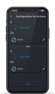
- – Next we need to select the TRIGGER – The TRIGGER is the relay in Sensor #2 – We are tracking when the relay in Sensor #2 turns ON (motion detected)
- – Now we choose the Action we would like to happen when this TRIGGER is TRUE
- – In this case we want to ACTIVATE a SCENE – in this case the first Scene created as per above
- – Save this
[IMAGE REQUIRED]
Now you must create a similar program to execute when the Sensor #2 times out – after not detecting motion for the period you programmed into the sensor when you first set it up.
Create another program except this time for the TRIGGER your are tracking the OFF state of Sensor #2 and the ACTION is to ACTIVATE a SCENE in this case the other scene created above.
[IMAGE REQUIRED]
More TRIGGERS and More Actions #
PROGRAMode does allow for tracking of up to 5 PIXIE master devices and for up to 10 or more ACTIONS to occur when ALL of those TRIGGERS are True.
In our example we have kept both simple with just one trigger and one action.
[IMAGE REQUIRED]
A Simpler Way to Do This – No Gateway Needed #
Whilst this is not strictly a sensor controlling a sensor, with a little planning up-fronr this approach below is far easier to deploy and no Gateway is needed either.
Like the scenario above we have 2 sensors – one at the top of the stairs and one at the bottom of the stairs.
The big difference is that NEITHER of these sensors is connected to any of the loads being controlled.
That is, they simply have an Active and a Neutral connected to power the devices.
- – The down lights over the stairs are connected to a PIXIE dimmer – SDD300BTAM
- – The LED strip is still controlled from the PIXIE LED Strip Dimmer – LT8915DIMBT
When a person approaches either sensor both light sources operate.
MASTERlink is the Key #
To achieve this we are going to user the MASTERLINK feature – which as of April 2024 is available in both PIXIE Master sensors.
MASTERlink operates with both the SAL PIXIE and PIXIE PLUS Apps.
MASTERlink allows each of the sensors to operate either another PIXIE Master device ( except another sensor ) or a Group.
MASTERlink is available in sensors with Firmware Version 1.3 or above.
What Steps are needed? #
Step 1 is to create a PIXIE Group which includes the 2 PIXIE master devices – the dimmer and the LED Strip dimmer
Step 2 is to head to Sensor#1 and set your MASTERLink function on.

Step 3 is to press the SET button to create your MASTERlink.

Step 4 is to define what the MASTERlink function from this sensor will do when it turns on and turns off. In this scenario you would select the GROUP created at STEP 1 and Save.
Step 5 is to repeat this process for Sensor #2
Once setup, the moment either sensor Turns ON or OFF ( Detects Motion / Sensor Times-Out according to Sensor Time out settings) the Group you have defined will operate.
This happens VERY quickly and is a much simpler set up than the initial example but it does depend on specific wiring on each project.


